인트로
오늘은 대망의 첫 통신 되시겠따.
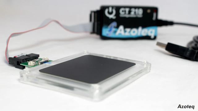
굳이 이 모듈을 구매한 이유는 수급이 안정적이고 크기도 모양도 적당하다 란 점이 있었지만
뭣보다 예제 샘플을 이렇게 예쁘게 제공해준단 점이 감동이었다.
누누히 말하지만 이렇게 주먹구구로 하는것보단 매뉴얼 정독 후 진행해야 삽질 안하고 일도 부드럽고 빠르게 진행된다.
그냥 내가 지금당장 뭔가 조물딱 거리고싶기 때문에 이런 무식한 방법으로 진행하는것일뿐...
예제분석
일단 코드를 까본다.
Arduino Example 실제 동작하는 아두이노 예제
여기서 다운받을수있다.
리드미도 있고 폴더를 열어보면 I2C.cpp IQS5xx.cpp, IQS5xx_Example_Code.ino 가 있다.
코드를 타고가면서 보는게 편하니까 VSCode를 켜서 폴더째로 열자.
IQS5xx Eaxmple_Code.ino
void setup()
{
	Serial.begin(115200);

	// Configure RDY pin
	//
	pinMode(RDY_PIN, INPUT);

	I2C_Setup();
	//
	// Clear the reset indication bit, so that from here on a reset can be
	// detected if the bit becomes set
	//
	IQS5xx_AcknowledgeReset();
	//
	// Read the version and display on the serial terminal
	//
	IQS5xx_CheckVersion();
	//
	// End the communication window
	//
	Close_Comms();
}
오늘은 체크버전까지 띄워보는걸 목표로 해본다.
일단 RDY 핀으로 인터럽트 받을 준비를 하는것이 보인다. 이친구도 Active_low 일것으로 보이는데 지금 필요한 핀은 아니니까 일단 넘어가자.
I2C_Setup() 은 TWI 관련 레지스터들을 리셋하는 코드가 들어가있다.
I2C_Write()
보통 i2c는 레지스터주소 한번 쓰기 + 한번읽기
혹은 레지스터주소 한번 쓰기, 데이터 한번쓰기 같은식으로 이루어진다.
이를 염두해두고 I2C_Write() 도 뚜껑을 따보려는데 I2C_Write2() 라는걸 먼저 갖다쓰고있었다.
바닥부터 까본다.
uint8_t I2C_Write2(uint16_t ui16RegisterAddress, uint8_t *pData, uint8_t ui8NoOfBytes)
{
	uint8_t	i;

	if(I2C_start() == FALSE) //I2C 모듈이 활성화되어있는지 체크
	{
		return(FALSE);
	}

	if(I2C_sendAddress(IQS5xx_ADDR<<1) == FALSE) //주소로 ACK 요청(Sleep 깨우기)
	{
		return(FALSE);
	}

	if(I2C_sendByte((uint8_t)(ui16RegisterAddress>>8)) == FALSE) //레지스터의 상위 8비트 쓰기
	{
		return(FALSE);
	}

	if(I2C_sendByte((uint8_t)ui16RegisterAddress) == FALSE) //레지스터의 하위 8비트 쓰기
	{
		return(FALSE);
	}

	for(i = 0; i < ui8NoOfBytes; i++) //데이터 길이만큼 연속으로
	{
		if(I2C_sendByte(*pData) == FALSE)
		{
			return(FALSE);
		}
		pData++;
	}

	if(I2C_stop() == FALSE)
	{
		return(FALSE);
	}
	return(TRUE);
}
ACK 요청을 한번 한 후 상위레지스터tx, 하위레지스터tx, 데이터만큼tx 로 이루어져있다.
이제 I2C_Write를 보자
//*****************************************************************************
//
//! I2C write function
//!
//! This function writes the provided data to the address specified.  If
//! anything in the write process is not successful, then it will be repeated
//! up till four more times.  If still not successful, it will write an error
//! message on the serial terminal.
//!
//! \param ui16RegisterAddress is the 16-bit memory map address on the IQS5xx
//! \param pData is a pointer to the first byte of a block of data to write
//! \param ui8NoOfBytes indicates how many bytes of data to write
//!
//! \return Boolean indicating success/fail of write attempt
//
//*****************************************************************************
uint8_t I2C_Write(uint16_t ui16RegisterAddress, uint8_t *pData, uint8_t ui8NoOfBytes)
{
	uint8_t ui8Retry = 4;

	ui8Success = I2C_Write2(ui16RegisterAddress, pData, ui8NoOfBytes);
	//
	// If comms was not successful, retry 4 more times
	//
	while((!ui8Success) && (ui8Retry != 0))
	{
		delay(5);
		ui8Success = I2C_Write2(ui16RegisterAddress, pData, ui8NoOfBytes);
		ui8Retry--;
	}

	if(ui8Success)
	{
		return(TRUE);
	}
	else
	{
		Serial.println("Comms write error");
		return(FALSE);
	}
}
I2C_Write2를 보고오니 별거없다.
Success 가 뜰때까지 혹은 Retry가 0이 될때까지 계속한다는것뿐.
그럼 이시점에서 실제 데이터 전송코드를 살펴보자
IQS5xx_AcknoledgeReset()
IQS5xx_AcknoledgeReset() 코드를 들여다본다.
#define ACK_RESET         		0x80
#define SystemControl0_adr 		0x0431	//(READ/WRITE)
//*****************************************************************************
//
//! Acknowledge the reset flag
//!
//! This function simply sets the ACK_RESET bit found in the SYSTEM_CONTROL_0
//! register.  By setting this bit the SHOW_RESET flag is cleared in the
//! SYSTEM_INFO_0 register.  During normal operation, the SHOW_RESET bit can be
//! monitored and if it becomes set, then an unexpected reset has occurred.
//! If any device configuration is needed, it must then be repeated.
//!
//! \param None
//!
//! \return None
//
//*****************************************************************************
void IQS5xx_AcknowledgeReset(void)
{
    static  uint8_t System_ctrl_0 = ACK_RESET;

    I2C_Write(SystemControl0_adr, &System_ctrl_0, 1);
}
0x0431 에다가 0x80을 쓰는게 전부인 코드다.
실제로 날아가는 데이터는 0x04, 0x31, 0x80 일것이다.
이로써 TX 코드는 대충 정리가 된다.
이제 수신코드를 확인해볼차례
I2C_Read()
uint8_t I2C_Read2(uint16_t ui16RegisterAddress, uint8_t *pData, uint8_t ui8NoOfBytes)
{
	uint8_t	i;

	if(ui8NoOfBytes == 0)
	{
		ui8NoOfBytes++;
	}

	if(I2C_start() == FALSE)
	{
		return(FALSE);
	}

	if(I2C_sendAddress(IQS5xx_ADDR<<1) == FALSE)// 디바이스의 ADDRESS 전송
	{
		return(FALSE);
	}

	if(I2C_sendByte((uint8_t)(ui16RegisterAddress>>8)) == FALSE) // 읽어올 레지스터 TX 윗자리바이트
	{
		return(FALSE);
	}

	if(I2C_sendByte((uint8_t)ui16RegisterAddress) == FALSE) // 읽어올 레지스터 TX 아랫자리바이트
	{
		return(FALSE);
	}

	if(I2C_start() == FALSE)
	{
		return(FALSE);
	}

	if(I2C_sendAddress((IQS5xx_ADDR<<1) + 0x01) == FALSE) // ADDRESS 전송+읽기모드
	{
		return(FALSE);
	}

	for(i = 0; i < ui8NoOfBytes; i++) //정해진 수만큼 읽기
	{
		if(i == (ui8NoOfBytes - 1))
		{
			if(I2C_receiveByte(0) == FALSE)
			{
				return(FALSE);
			}
		}
		else
		{
			if(I2C_receiveByte(1) == FALSE)
			{
				return(FALSE);
			}
		}
		*pData = TWDR;
		pData++;
	}
	if(I2C_stop() == FALSE)
	{
		return(FALSE);
	}
	return(TRUE);
}
그리고
uint8_t I2C_Read(uint16_t ui16RegisterAddress, uint8_t *pData, uint8_t ui8NoOfBytes)
{
	uint8_t ui8Retry = 4;

	ui8Success = I2C_Read2(ui16RegisterAddress, pData, ui8NoOfBytes);
	//
	// If comms was not successful, retry 4 more times
	//
	while((!ui8Success) && (ui8Retry != 0))
	{
		delay(5);
		ui8Success = I2C_Read2(ui16RegisterAddress, pData, ui8NoOfBytes);
		ui8Retry--;
	}

	if(ui8Success)
	{
		return(TRUE);
	}
	else
	{
		Serial.println("Comms read error");
		return(FALSE);
	}
}
이친구도 마찬가지로 재시도를 위한 래핑코드로 이루어졌다.
그럼 이 순서대로 간단하게 nRF로 옮겨보자.